

Introduction
In both GIS (Gas Insulated Substation) and AIS (Air Insulated Substation) facilities, partial discharges (PD) represent a silent threat that can compromise the insulation system and service continuity. Early detection is essential to prevent costly failures and to plan effective maintenance interventions.
For this reason, both offline and online PD testing have become essential tools in the predictive maintenance of transformers, cables, generators, and other critical substation assets. This article explores the main methods, benefits, and the strategic role of ENERGISAR S.A.S. as a specialist in advanced diagnostics and the execution of field tests with high technical standards.
What Are Partial Discharges and Why Are They Relevant in GIS Substations?
According to IEC 60270, partial discharges are defined as localized electrical discharges that partially bridge the insulation between conductors and may or may not occur adjacent to a conductor. This means that a partial discharge can occur in any area of the insulation, particularly in weakened or deteriorated zones.
In essence, partial discharges are localized electrical phenomena that occur within an insulation system without causing a complete breakdown between conductors. They are typically triggered by electric stress or dielectric overstress when equipment is subjected to high voltajes.
In GIS systems, where insulation is provided by pressurized SF₆ gas, these discharges can originate from internal contamination, manufacturing defects, assembly errors, or harsh operating conditions. Because GIS is a sealed system, internal faults are not visible and require specialized detection techniques.
Partial discharge testing, as an indicator of insulation system performance, enables the identification of defects that other dielectric tests—such as insulation resistance, dissipation factor (tan delta), or leakage current—may not detect. Its distinguishing feature lies in its ability to pinpoint the exact location of a defect before it leads to complete failure.
Partial discharges (PD) can take on different forms depending on their location and the type of defect present in the insulation system. Each type has distinct characteristics, specific causes, and an associated risk level. Understanding them is essential for accurate diagnostics and an effective maintenance strategy.
Below are some of the main PD types identified by ENERGISAR S.A.S. based on its field experience:
- Internal Discharges
- Surface Discharges
- Corona Discharges
- Slot Discharges
- Floating Discharges
These occur inside the insulating material, typically in air bubbles or delaminated areas. They usually originate from manufacturing defects, poor resin impregnation, or thermal aging due to operational stress.
Why are they a concern?
They are highly destructive and, if undetected, can lead to the complete failure of the insulation system. These discharges are especially dangerous because they are invisible and gradually degrade insulation from within.
- Surface Discharges
These propagate along the surface of insulating materials, such as winding heads, cable coatings, or exposed areas of transformers. This is one of the most hazardous PD types, as it can rapidly erode insulation and initiate electrical arcing.
They are typically caused by adverse environmental conditions—surface contamination, humidity, water ingress—or poor insulation design. Conductive particle buildup on insulators can also provoke this discharge.
Why are they a concern?
Even if audible or visible, they can progressively erode the material’s surface, eventually causing punctures if left unchecked.
- Corona Discharges
They appear when the electric field ionizes the air around energized edges or conductive elements. They are characterized by a visible glow, a distinctive buzzing sound, and ozone generation. Often underestimated, they nonetheless contribute to the progressive degradation of insulation and energy losses.
Why are they a concern?
Though seemingly harmless, over time they deteriorate insulation and accelerate aging, increasing the risk of failure and inefficiency.
- Floating Discharges
These arise between metallic elements that are not properly grounded. Loose components such as screws, clamps, or metal sheets can behave as floating electrodes and generate sudden discharges when electrically charged.
Why are they a concern?
This type of partial discharge generates erratic and hard-to-identify signals, posing a significant risk of evolving into a full arc.
Partial Discharge Measurement Methods: Key Techniques for GIS and High-Voltage Equipment
There are multiple methods for detecting partial discharges (PD), ranging from conventional techniques to advanced, non-invasive solutions. ENERGISAR S.A.S. collaborates with strategic partners that provide specialized equipment for PD measurement.
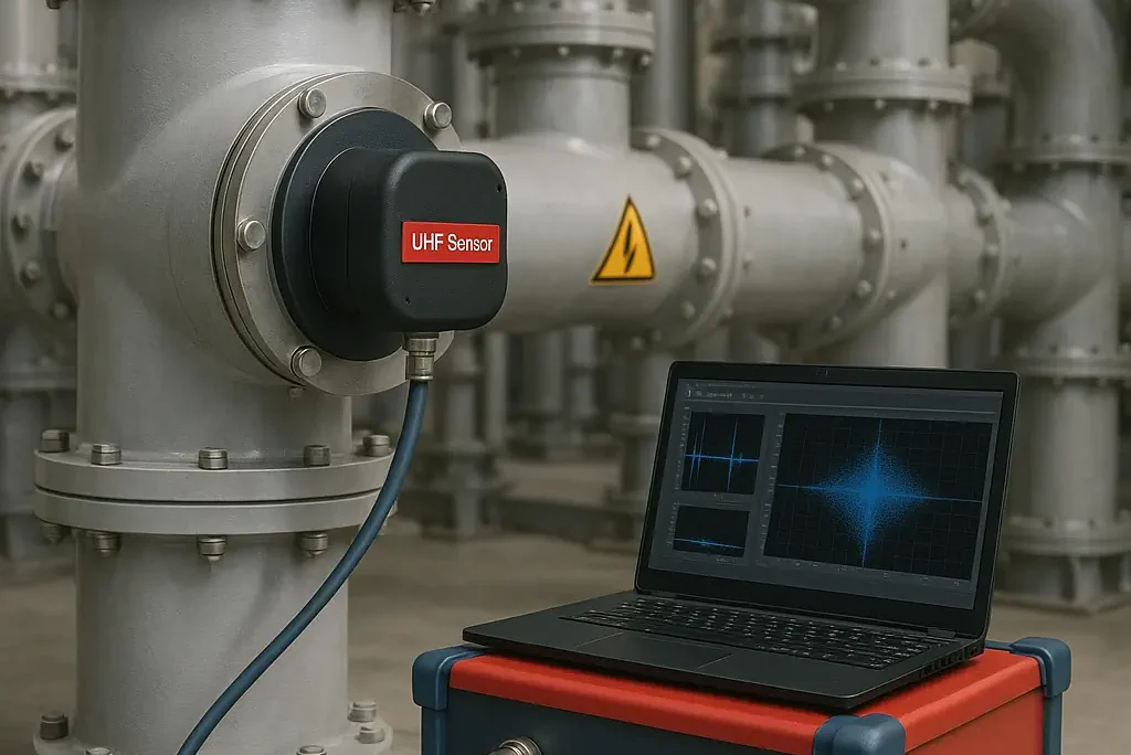
Various types of sensors are used in PD detection, including Ultra High Frequency (UHF) couplers, High-Frequency Current Transformers (HFCT), ultrasonic sensors, and Transient Earth Voltage (TEV) detectors.
- Conventional Method (IEC 60270)
Title:: High-voltage test techniques – Partial discharge measurements
Main Application: Measurement of partial discharges in high-voltage electrical equipment.
Key Features:
- Serves as the standard baseline for PD measurement in high-voltage systems.
- Defines measurement methods, test conditions, instrumentation, and calibration procedures.
- Commonly applied in high-voltage test laboratories for type and routine testing.
- Involves the use of capacitive measuring couplers, filters, amplifiers, and data recorders.
- Does not specify acceptance criteria — these are defined by product-specific standards.
Principle: Measures apparent charge (in pC) using capacitive coupling.
Test Setup Example: The standard outlines several voltage injection options for PD testing. The most common includes:
- Measuring inception voltage (the voltage at which PD starts)
- Measuring extinction voltage (the voltage at which PD ceases)
Typical Configuration Includes:
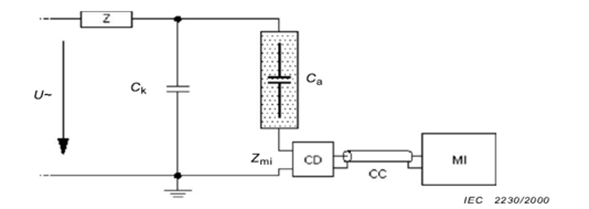
Figura 1. Configuración para el método convencional acorde a la norma IEC 60270
- High-voltage source
- Test object (Ca)
- Coupling capacitor (Ck)
- Coupler (Coupling Device – CD): used to inject calibration signals and extract PD signals
- Impedance adapter or filter (Z)
- Measuring instrument (MI): wide-band or narrow-band
- Pulse calibrator (Qk)
Before performing any measurements, the equipment must be calibrated using a pulse calibrator that simulates PD by injecting a known charge — e.g., 10 pC, 50 pC, or 100 pC in a short time (≤1 µs).
Calibration Requirements:
- Maximum allowable measurement error: ±10% or ±1 pC (whichever is greater).
- Calibration pulses must be applied with sufficient repetition to simulate a real condition.
- UHF Method (Ultra High Frequency) – [100 MHz to 2 GHz]
Partial discharges can be observed as pulses whose shape varies depending on the discharge intensity. These pulses generate ultra high-frequency oscillations in the system, propagating at the speed of light. One of the most effective ways to detect these pulses is through UHF antennas, which—when combined with an appropriate measuring system—allow for the identification of PD sources. The detected signal’s magnitude depends greatly on the defect’s location and, to a lesser extent, on its orientation and the coupler used.
Complementary analysis can also be conducted using specialized tools like spectrum analyzers, which help identify the specific type of PD being detected.
The signal-to-noise ratio—and thus the sensitivity of the UHF method—is a key factor in its effectiveness. These aspects can be improved using amplifiers, filters, and suitable couplers. In SF₆ gas-insulated GIS substations, the UHF and acoustic methods are among the most widely used for PD detection.
- Principle: Detects high-frequency electromagnetic waves generated by PD inside the GIS compartment.
- Sensors:
- Internal sensors – UHF antennas integrated during GIS manufacturing
- External couplers/sensors – Installed as needed
- Advantages:
- High immunity to environmental electrical noise
- Suitable for both offline measurements and continuous online monitoring
- Does not interfere with the equipment’s normal operation
- Compatible with built-in GIS sensors or external UHF couplers
- Typical Usage:
- Commissioning tests
- Permanent condition monitoring in GIS
The UHF method has proven to be as sensitive and effective as the conventional IEC 60270 method in detecting PD sources, especially in low-noise environments. However, it does not provide a precise value for apparent charge (in pC) as the IEC 60270 standard does.
- TEV (Transient Earth Voltage)
- Principle: This method detects high-frequency voltage transients that propagate along the metallic enclosure of the equipment, generated by internal partial discharges.
- Application: Internal PDs, especially in metal-enclosed switchgear and medium-voltage equipment.
- Advantages:
- Non-invasive technique
- Ideal for metal-enclosed medium-voltage switchgear
- Fast and easy to deploy
- Effective for detecting surface and internal PD in compact, air-insulated systems
- HFCT/RFCT – High-Frequency Current Transformers
- Principle: This method uses high-frequency current sensors—HFCT (High-Frequency Current Transformer) or RFCT (Radio-Frequency Current Transformer)—installed around grounding conductors or metallic shields to detect transient PD pulses traveling to ground.
- Application: Primarily used for online monitoring of power cables, including those connected to GIS systems.
- Advantages:
- Allows PD testing without de-energizing the system
- Requires minimal resources and setup time
- Detects high-frequency current pulses caused by partial discharges that propagate through the grounding path.
These sensors are especially effective for non-intrusive diagnostics in energized installations. Because the sensors clamp externally around ground conductors, they are easy to install and do not interfere with normal operation.
- Acoustic Method
The acoustic method for detecting partial discharges in GIS substations is based on capturing mechanical signals (acoustic waves) generated by two main phenomena:
- Impacts of moving particles against the metal enclosure
- Pressure waves produced by PD events in fixed defects
These waves propagate through the SF₆ gas and are transmitted to the metallic enclosure, where they can be detected by external acoustic sensors.
Sensors Used:
- Accelerometers: Detect acceleration on the GIS surface.
- AE Sensors (Acoustic Emission): Detect vibration velocity; operate above 100 kHz.
Advantages:
- High sensitivity to loose particles (signal frequencies above 1 MHz)
- Useful for localizing defects using time-of-flight (ToF) analysis
- Complements UHF and conventional methods
- Non-intrusive and easy to apply externally
Typical Applications:
- Diagnostics during maintenance or commissioning
- Especially useful for detecting loose metallic particles, protrusions, or floating elements
Effectiveness depends on the distance to the defect and the sensor’s location, as signals are attenuated when passing through flanges or mechanical sections.
Limitations:
- Signal strength decreases with distance (high attenuation)
- Sensitivity is limited if the sensor is not placed close to the defect
- Challenging to identify the exact PD type
- Susceptible to external mechanical noise
- Cannot measure apparent charge (pC) like the IEC 60270 method
Among the methods previously described, in GIS-type substations, the UHF method remains the most reliable and recommended—both for one-time testing and continuous system monitoring. For ENERGISAR S.A.S., this method has proven essential in delivering accurate and trustworthy diagnostics, resulting in high customer satisfaction.
However, combining multiple techniques provides a more comprehensive view of the insulation condition and significantly enhances diagnostic precision.
Sensors for Partial Discharges (PD)
The market offers a wide variety of sensors for detecting partial discharges (PD), each designed to capture different physical phenomena associated with these events. Additionally, there are advanced measurement systems with independent channels capable of simultaneously detecting signals across multiple frequency ranges. This flexibility allows multiple sensors to be configured and used in a single diagnostic session, leading to more comprehensive analyses and improved localization and characterization of PD sources in high-, medium-, and low-voltage systems.
Below are the most common sensor types, several of which were mentioned in the earlier detection methods:
- AE Sensor (Acoustic Emission): Detects acoustic waves generated by the energy released during a partial discharge. Particularly effective for identifying PD in air or in solid materials with surface accessibility. Common applications include power transformers and high-voltage switchgear.
- HFCT Sensor (High-Frequency Current Transformer): Measures high-frequency currents induced in grounding conductors, typical of PD activity. Widely used for power cables and transformers, allowing for non-invasive detection without de-energizing the system.
- UHF Sensor (Ultra High Frequency): Captures very high-frequency electromagnetic signals (in the MHz range) emitted by PD. Especially suitable for shielded equipment such as GIS (Gas Insulated Switchgear) and sealed power transformers, where lower-frequency or acoustic signals may be attenuated. Also used in HV cables and switchgear systems.
- TEV Sensor (Transient Earth Voltage): Detects transient voltages that propagate along the surface of metallic equipment due to internal PD. Commonly applied in medium-voltage switchgear insulated with air or solid materials such as epoxy resin.
At ENERGISAR S.A.S., the selection and combination of these sensors are tailored to each client’s specific installation, enabling high-precision diagnostics across a broad range of applications.
Methods for Partial Discharge Diagnosis
Reflectometry and Phase-Resolved Partial Discharge Analysis (PRPD) are advanced techniques used in the interpretation and diagnosis of partial discharges (PD), each with different approaches and applications.
1. Time Domain Reflectometry (TDR)
What is it?
TDR is a technique based on the propagation and reflection of electrical pulses along a conductor (e.g., power cables). When there is a discontinuity or defect—such as active partial discharge—part of the pulse reflects back, and this reflection can be detected and analyzed.
How is it applied in PD diagnosis?
In the context of PD, reflectometry not only detects the presence of a discharge but also helps locate the defect’s position along the cable or in the GIS connections.
Key Features:
- Highly useful in medium- and high-voltage cable systems.
- Provides accurate distance-to-fault estimation.
- More commonly used in offline tests, though some online configurations exist.
Limitations:
2. Phase-Resolved Partial Discharge Analysis (PRPD)
What is it?
PRPD is a technique that records the amplitude, frequency, and phase angle of each PD event in relation to the power voltage cycle (typically 50 or 60 Hz AC). Its goal is to associate each PD pulse with the phase angle at which it occurs, revealing characteristic patterns based on defect type.
How is it applied?
During a PD measurement, the test equipment detects individual pulses (from HFCT, UHF, or current signals) and synchronizes them with the applied voltage waveform. This synchronization generates a 3D map known as the PRPD diagram, typically plotted as:
- X-axis: Voltage phase (0° to 360°)
- Y-axis: Discharge magnitude (in pC, mV, or dBm depending on method)
- Z-axis or color scale: Number of occurrences (density)
Each PD type—internal, surface, corona, etc.—produces a distinct pattern in the PRPD plot, enabling identification and classification of defects.
Advantages:
- Identifies PD type without physical intervention
- Useful in factory, laboratory, and field testing.
- Applicable in GIS when used with appropriate sensors (e.g., UHF with phase synchronization).
Limitations:
- Requires the test operator to be experienced in interpreting signal patterns (Requires experience to interpret patterns correctly).
- PRPD patterns evolve over time and are not static.
- The signal must be synchronized with the power supply to ensure reliability.
- Can be affected by electrical noise if proper filters or sensors are not used.
Example Patterns:
Some examples of patterns that may be observed using the phase-resolved method, depending on the type of discharge, are as follows:
- Corona discharges :
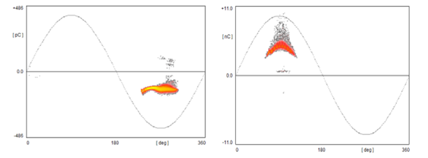
Figure 2. Distinct patterns for positive and negative events in air [1]
- Surface discharges :
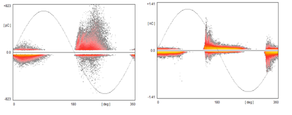
Figure 3. Vary depending on medium (air vs. oil) [1]
- Internal discharges:
| Figure 4. Phase-resolved method: reference pattern for internal-type discharges. [1] |
According to IEC 62271-203, the maximum allowable apparent charge for partial discharges must not exceed 5 pC for equipment rated above 52 kV insulated with SF₆ gas (GIS).
However, some components—such as liquid-insulated voltage transformers, oil-immersed devices, or those with solid insulation—may have higher acceptable PD levels based on their specific product standards.
This clarifies that certain equipment, depending on its design or applicable standard, may tolerate higher partial discharge values without being considered defective.
At ENERGISAR S.A.S., acceptance criteria are always applied in accordance with international standards, manufacturer specifications, and the criticality of the asset, ensuring both safety and long-term reliability.
ONLINE and OFFLINE Testing
Depending on the nature of the test, partial discharge (PD) measurements can be carried out with the equipment energized (ONLINE) or de-energized (OFFLINE)
OFFLINE Partial Discharge Testing
Offline testing is performed with the equipment completely de-energized and isolated from both the load and the power source. These tests are typically conducted during commissioning, scheduled maintenance, or detailed diagnostics. They allow the application of controlled voltages—often higher than nominal levels—to stress the insulation and detect latent defects.
Key Characteristics:
- High sensitivity: Capable of detecting even minimal defects under controlled conditions.
- Technologies used: UHF coupling systems integrated into the GIS, capacitive sensors, and phase-resolved analysis (PRPD).
- Advantage: Performed without interference from power grid noise.
- Limitation: Requires shutdown and disconnection, so it must be carefully scheduled.
These tests are ideal for detecting post-installation issues, evaluating assembly quality, and verifying insulation condition after major interventions.
ONLINE Partial Discharge Testing
Online testing is performed with the substation energized and in normal operation. This method allows real-time monitoring of the insulation’s behavior under actual operating conditions—without service interruption.
Main Advantages:
- No disconnection required: Ideal for critical or hard-to-access installations.
- Real-time monitoring: Enables trend analysis and data-driven maintenance decisions.
- Early detection: Identifies incipient defects before they pose a serious risk.
For these tests, UHF sensors are either permanently installed in GIS compartments or temporarily attached to capture electromagnetic emissions from PD. The sensors are connected to analyzers that interpret the signals and generate reports with specific patterns indicating the type and evolution of the defect.
Conclusion
Partial discharges are early indicators of insulation degradation in medium- and high-voltage systems. Their detection in GIS substations is especially critical due to the severity of internal faults and the limited accessibility of the system.
Methods such as UHF and acoustic detection make it possible to identify these discharges, though their sensitivity depends on factors such as the defect type and location, the coupler, the measurement equipment, and ambient noise conditions. While UHF offers broader coverage and higher noise immunity, acoustic methods are more limited in range but valuable for locating mechanical issues like loose particles.
Timely detection through proper testing enables strategic maintenance decisions, prevents costly and catastrophic failures, and helps optimize the service life of critical assets.
ENERGISAR S.A.S. remains at the forefront of these evolving techniques, continuously integrating state-of-the-art technology to deliver more precise, reliable, and tailored measurements to meet each client’s specific needs.
ENERGISAR S.A.S. has a highly qualified technical team and state-of-the-art technology to perform partial discharge testing both offline and online, fully tailored to the specific requirements of each installation.
If you’re looking to strengthen your predictive maintenance strategy and ensure the reliability of your electrical assets, contact us today and schedule a consultation with our PD diagnostics specialists.
References
[1] M. G. Niasar, “Partial Discharge Signatures of Defects in insulation Symtems Consisting of Oil and Oilimpregnated Paper,” KTH School of Electrical Engineering, 2012. Web: https://www.diva-portal.org/smash/get/diva2:572145/FULLTEXT01.pdf
[2] IEC 60270 Standard CONSOLIDATED VERSION. High-voltage test techniques – Partial discharge measurements. Edition 3. 1 201 5-1 1