

Introduction
In previous articles published by EnerGISar S.A.S., topics of great importance for understanding the services they offer have been discussed, broadening the perspective and comprehension of what a GIS substation is and what it comprises. As has been observed, GIS substations have been an innovative solution with an extensive list of benefits; however, given the complexity of their design and the high voltages they can withstand, it is essential to perform electrical tests—particularly high-voltage and partial discharge tests—to ensure the integrity not only of the insulation but also of the system as a whole. This is necessary to prevent failures that could compromise the continuity of energy supply, a problem that companies seek to avoid due to its economic implications. This article focuses on exploring high-voltage testing in GIS substations, the factors that can compromise insulation integrity, and the importance of these tests for safety and operational efficiency.
Importance of High-Voltage Tests in GIS Substations
High-voltage tests in GIS substations are essential for assessing the ability of insulating materials and electrical components to withstand elevated voltages without damage or failure. These tests help identify manufacturing or installation defects, as well as insulation degradation that could lead to system failures, unplanned power outages, and safety risks for personnel. Additionally, compliance with the international standard IEC 62271-203 is crucial for these tests as it regulates the procedures and voltage levels to ensure the safety and reliability of electrical installations.
Factors That Affect Insulation Integrity in a GIS Substation
The insulation integrity in GIS substations can be compromised by several factors, including:
- Protrusions or Fixed Particles: Imperfections on the surface of insulating material or embedded metallic particles can create localized electric fields, which may trigger corona effects, partial discharges, and subsequent dielectric failures.
- Mobile Particles: Small metallic particles moving within the gas-insulated compartment can cause electric arcs, especially if they come into contact with or create paths that reduce the insulation distance with the high-voltage components.
- Interstices in Insulators: Void spaces or inclusions in solid material insulators can cause voltage accumulation, which in turn may lead to partial discharges or insulation failures.
- Particulate Material: During the GIS component assembly processes, there is a possibility that environmental materials such as dust, metallic particles, and assembly or cleaning chemicals may enter the compartments. These materials can become trapped inside the compartments, potentially causing failures during testing (flashover) and in future operations of the equipment. EnerGISar S.A.S. upholds the strictest standards and procedures to ensure that these substances and components do not enter the system.
- Equipment Transportation: During transportation, SF6 equipment or compartments may suffer impacts that could affect internal components and insulation, thus disrupting their performance. Therefore, the transportation of GIS substation equipment and SF6 gas must be conducted with the necessary precautions and manufacturer recommendations for both storage and transport, as well as lifting processes. EnerGISar S.A.S. is equipped with specialized equipment (trailers, cranes, treatment machines, and certified personnel) and has a well-developed planning process to support and ensure the good condition of components in all necessary processes before and during activities.
- Damage During Equipment Handling: Cracks in insulating supports, contaminants introduced during the handling of GIS components, ingress of materials, tools, and impacts on equipment can weaken insulation, increasing the risk of electrical failures. This can also lead to downtime and delays in the execution of activities and final project delivery.
- Poor Contact: Deficient connections between electrical components due to factors such as failure to check factory-sent bolted connections, lack of step-by-step verification during site assembly, installation of contacts not corresponding to diagrams or plans provided by manufacturers, among other factors, can cause electrical failures and affect the integrity of equipment insulation. Therefore, it is crucial to follow manufacturer instructions and criteria, support information with international standards, and as in the case of EnerGISar S.A.S., execute procedures developed from the management system (complying with torque specifications between parts and materials). Failure to inspect and follow these recommendations may result in overheating, electrical arcing, hot spots, or false contacts, compromising the integrity and operation of the GIS substation, increasing the risk of failures under mechanical, seismic, and electrodynamic stresses, which may be detected during contact resistance tests and, if critical, during high-voltage testing (in some cases).
- Damage to System Integrity Due to Loss of Pressure/Gas Density: The reduction in the pressure or density of SF6 gas in GIS compartments can decrease its insulating capability, increasing the risk of dielectric failures. Therefore, tightness tests of the system and inspection of SF6 gas levels and pressure in each compartment are crucial, verifying the proper operation of density meters and SF6 gas levels. It is essential to check these factors before high-voltage testing and system energization.
Types of High-Voltage Tests in GIS Substations
Before commissioning a gas-insulated substation (GIS), it is essential to perform dielectric tests to verify the integrity of the insulation and detect potential irregularities such as damage during handling, transportation, storage, improper installation, or the presence of foreign bodies—factors that, as previously mentioned, can impact insulation quality.
Different methods are available for high-voltage tests in GIS substations; according to the IEC 62271-203 standard, the following testing options are specified:
- Applied Voltage Test (AC) or “Short-Duration Power-Frequency Withstand Tests”: These tests involve applying a voltage higher than the nominal rating of the equipment or system using an AC high-voltage resonant system, gradually increasing the voltage to the specified level. This ensures that the insulation can withstand overvoltages without failure, thereby guaranteeing safe and reliable operation of the GIS.
- Impulse Voltage Tests: These are divided into two types:
- Oscillating lightning impulse (OLI): These tests are useful for detecting defects in insulation and abnormal field configurations. Typically, they are performed when AC high-voltage tests cannot be conducted alongside partial discharge tests.
- Oscillating switching impulse (OSI): These tests are useful for identifying the presence of contamination in the system, as well as abnormal field configurations. They are usually conducted when AC high-voltage tests or Oscillating Lightning Impulse tests cannot be performed.
- Partial Discharge (PD) Test: Partial discharges are small releases of electrical energy that occur at weak points in the insulation without completely breaking through it. The partial discharge test is crucial for detecting minor defects that may not be identified during applied voltage tests, such as mobile particles, voids in insulators, and manufacturing defects. These tests allow for the identification not only of the presence of defects but also of their type and location, enabling early and preventive intervention.
Typically, the partial discharge test is conducted alongside the applied AC voltage test; however, EnerGISar S.A.S. will provide more detailed information on the application of this test in upcoming articles. For more precise information on the high-voltage tests mentioned in this article, refer to the IEC 62271-203 standard or the IEEE C37.122 standard.
Connections for High-Voltage Tests
For high-voltage testing, there are various connection methods to the GIS substation. These include the following:
- Air connection to the GIS bushing.
- Direct connection using a GIB (Gas-Insulated Busbar).
- Induced voltage through the secondary winding of the VT (Voltage Transformer) of the GIS substation.
To physically observe the connections mentioned above, refer to Figure 1, Figure 2, and Figure 3.

Figure 1. Connection of the testing equipment to the phase bushing of the GIS substation under test.

Figure 2. Connection of the testing equipment directly to the main busbar with a phase selector. Phase of the GIS substation under test.

Figure 3. Connection of the testing equipment directly to the Power Potential Transformer (Power PT). The secondary winding connection steps up the primary voltage. Phase of the GIS substation under test.
Applied AC Voltage Test – Short-Duration Power-Frequency Withstand Tests
These tests are particularly sensitive for detecting contaminants (including conductive particles) and, in most cases, are also sufficient for identifying abnormal dielectric configurations in the system. A resonant alternating current generator is typically used, operating in frequency ranges of 10 to 300 Hz according to the IEC 62271-203 standard or 30 Hz to 300 Hz according to the IEEE C37.122 standard.
Circuit representations for this type of test can be seen in Figures 4 and 5.
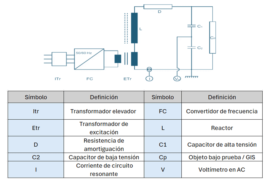
- Figure 4: Example of a Resonant Frequency Circuit for On-Site High-Voltage Testing. Obtained from [1].
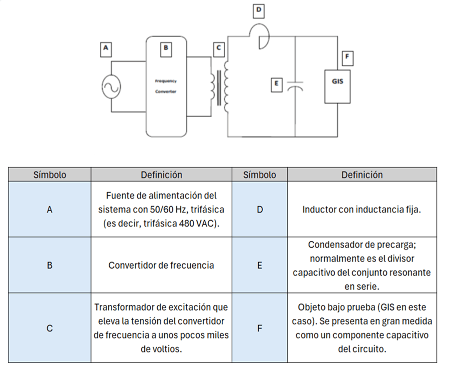
- Figure 5: Circuit connection of the testing equipment to the phase bushing of the GIS substation under test. Obtained from EnerGISar S.A.S. procedures for electrical testing in GIS substations.
In Figure 4 and Figure 5, the GIS substation is shown as “Cp” or “F,” represented as a capacitive component in the circuit.
It is important to ensure a safe distance during the setup of the high-voltage resonant equipment; the distances are maintained between the inductive reactor and the excitation transformer to prevent any discharge.
Table 1. Safety distances between the reactor and the excitation transformer
| Voltage test (kV) | 50 | 100 | 200 | 500 | 750 | 1000 |
|---|---|---|---|---|---|---|
| Safe distance (m) | 1.2 | 1.5 | 3.0 | 5.5 | 7.5 | 12 |
To calculate the natural frequency of the system, the following equation is used:
Equation 1. Calculation of the Natural Frequency of the System

Where “L” will be the inductance of the high-voltage reactor and “Cp” the capacitance of the respective GIS section.
EnerGISar S.A.S. has a procedure specifically dedicated to this type of testing and also employs qualified personnel for its execution. The company’s staff not only performs the necessary calculations for preparing the test but also handles the connection between the GIS and the testing equipment (topological configuration of the substation to be tested, definition of sections, and number of required tests indicating the location of the resonant equipment).
Voltage Levels for High Voltage Tests According to IEC 62271-203:2011
For high voltage tests, the applied voltage depends on the nominal voltage of the GIS being tested. The following voltage levels are specified according to the IEC 62271-203:2011 standard.

Recommendations and Testing Duration – IEC 62271-203
- For nominal voltages below 170 kV: Procedure A
- Perform the applied voltage test with the resonant system using the values specified in column 2 of Table 2 for a duration not exceeding 1 minute for the Uds value.

- For nominal voltages equal to or greater than 245 kV: Procedure B
- Perform the applied voltage test with the resonant system using the values specified in column 2 of Table 2 for a duration not exceeding 1 minute for the Uds value.
- Along with the high voltage test, carry out partial discharge measurements.

- Alternative to Procedure B for voltages equal to or greater than 245 kV: Procedure C
- Perform the applied voltage test with the resonant system using the values specified in column 2 of Table 2 for a duration not exceeding 1 minute.
- Along with this test, conduct the on-site lightning impulse withstand voltage test as represented in column 4 of Table 2.

- Procedure by Cycles for Conditioning in High Voltage Testing
- As previously specified, the high voltage test is a test where the voltage is gradually increased to the value specified in Table 2. The gradual or cyclic increase in voltage is known as conditioning for the high voltage test.
- Conditioning 1: 100 kV for 15 minutes
- Conditioning 2: 174 kV for 3 minutes
- High Voltage Test: 235 kV for 1 minute according to IEC 62271-203.
Graphically:
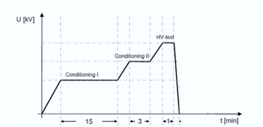
- Figure 6: High Voltage Test Cycle with Conditioning
The previous recommendations are according to the IEC 62271-203 standard.
Acceptance Criteria
The applied voltage test is a pass/fail procedure. If an electrical disruption occurs during the test, it will be considered a failure. If the operator decides to perform another injection, they must determine the number of allowable attempts for re-injecting the circuit under test (up to a maximum of 3 attempts), since any minor particulate material may be disintegrated during the initial test. If the fault persists, the operator should halt the test and inspect the compartment where the discharge is detected, as the test must withstand the applied voltage for the duration specified by the standard. Conversely, if the GIS substation does not show any discharges, the test will be considered successful, and the injection will proceed to the subsequent phases.
Conclusion
High voltage and partial discharge tests are essential for ensuring the integrity of insulation in GIS substations. Through these tests, defects that could compromise the safety and efficiency of the installation can be identified, allowing for early intervention to prevent costly and dangerous failures. EnerGISar S.A.S. is committed to conducting these tests with the highest standards of quality and safety, utilizing advanced equipment and trained personnel to ensure the optimal performance of GIS substations.
If you have any questions or would like to learn more about the electrical tests performed by EnerGISar S.A.S. on GIS substations, please feel free to reach out to them.
References
[1] ABB. Power and Productivity for a Better World. ABB now Hitachi: SF6 Gas-insulated Switchgear High-voltage On-site Testing of GIS Type ELK. Documento de la empresa ABB.
[2] Dexotech Power. High Voltage Testing and Partial Discharge Measurements in Gas Insulated Switchgear (GIS). High Voltage Testing and Partial Discharge in GIS. Recuperado de https://dexotechpower.com/field-testing/gas-insulated-switchgear-gis-partial-discharge/. Consultado el 22 de agosto de 2024.
[3] International Electrotechnical Commission. (2011). IEC 62271-203: High-voltage switchgear and controlgear – Part 203: Gas-insulated metal-enclosed switchgear for rated voltages above 52 kV (Edición 2.0).